 SumiCAD
Quick start: from an empty project to a permit set
Fifteen short steps take a small two-storey timber house from a new install to a published 確認申請 PDF. The project is fictional (見本 means "sample"); type your own data when you do it for real. About 30 minutes the first time.
SumiCAD prepares the documents and the calculations. A licensed 建築士 checks, signs and submits them.
Tip: the Navigator's PROJECT STEPS line (right column, top) always shows the next step; click it to open the panel or tool that does it. Every action below is one undo step (Ctrl+Z).
1. Set up your firm
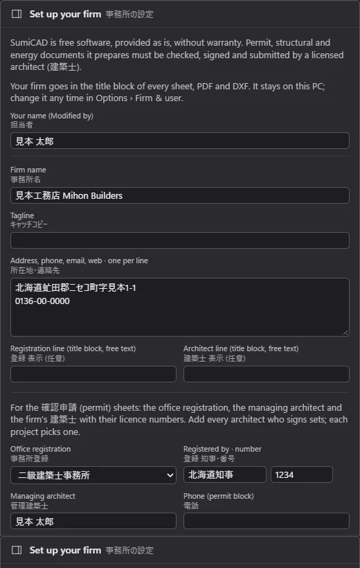
On the first start SumiCAD asks for your firm once. Fill in Your name, Firm name, the address lines, the Office registration (二級建築士事務所, 北海道知事, 1234) and the Managing architect. Under Architects, click Add architect and fill Name 氏名, Grade 資格, Registered by 登録 and No. 番号. Click Save firm.
You should now see: the start screen. Change the firm later in Options › Firm & user settings….
2. Start from the office template
Click Office standard (built in) under NEW FROM TEMPLATE. It brings the layout book (drawings, permit and structure sheets), the build-ups and the layer combinations. New project starts empty, without sheets.
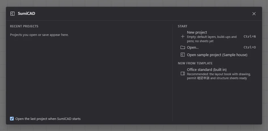
You should now see: an empty plan, the Empty project card and PROJECT STEPS 0 / 10.
3. Project info
Click Next: Project info in the Navigator (or File › Project info (client, site)…). Type the Project name (見本邸 新築工事), Client name (見本 花子), Site address, Lot number (地番) and Zoning (用途地域).
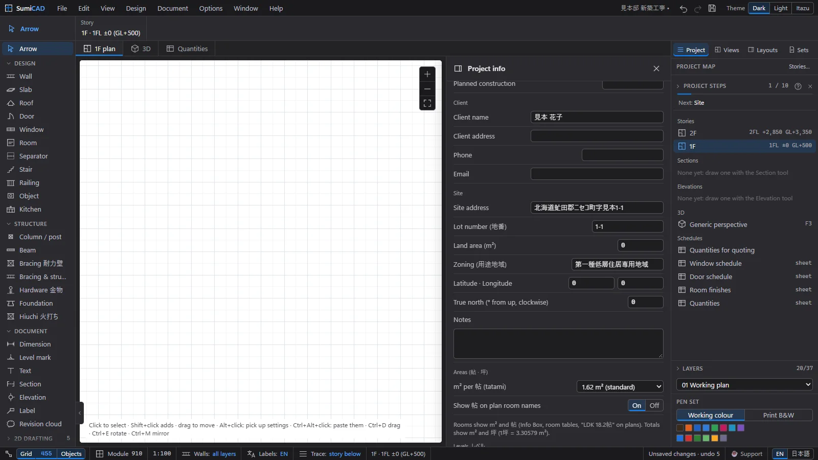
You should now see: the title bar shows the project name; the prefecture and town are guessed from the address (Document › Permit data 確認申請… › Region, check it there).
4. Site: position, boundary and road
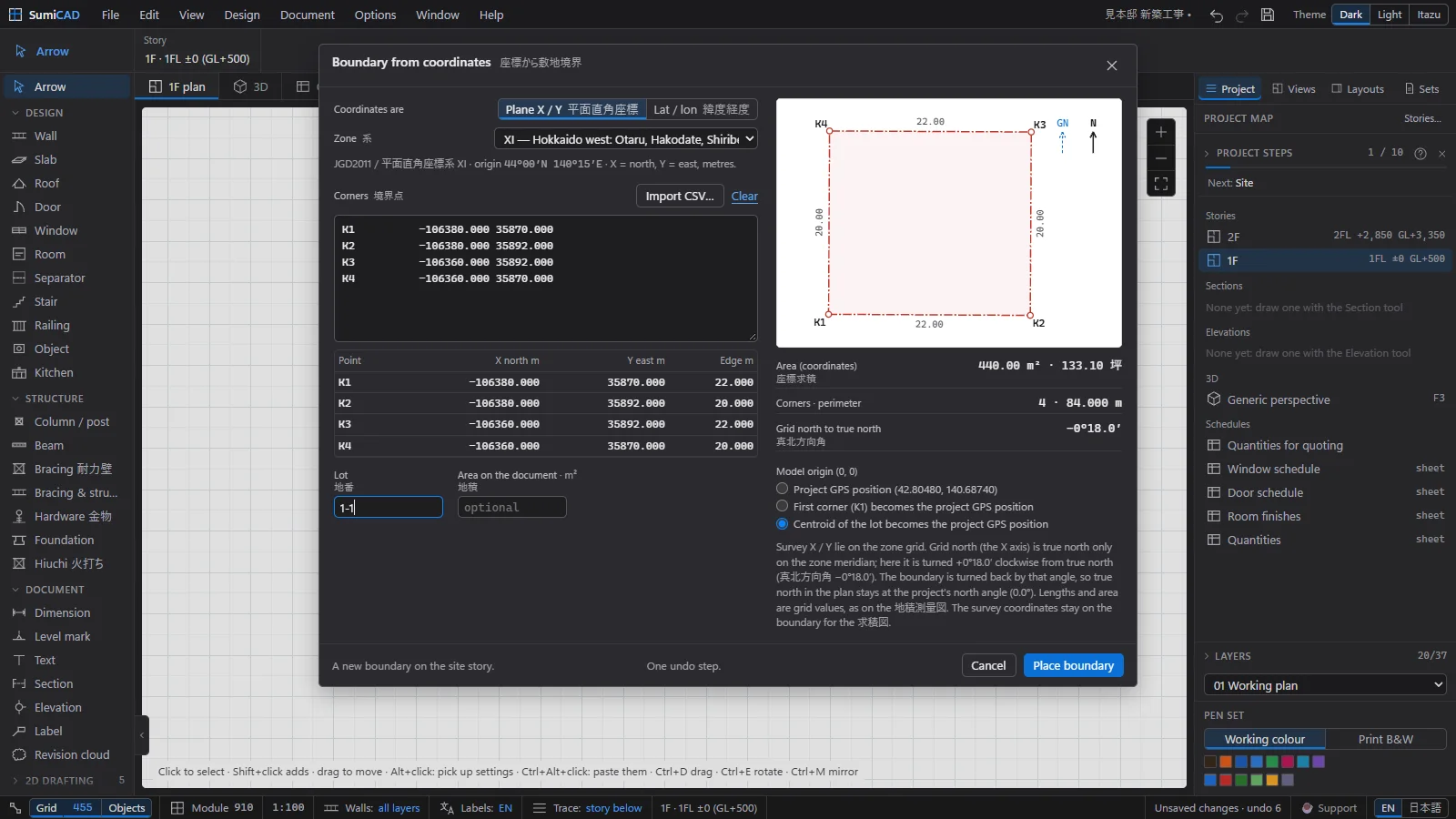
Click Next: Site. In the Site panel, paste the GPS position into Paste a position (42.8048, 140.6874), then click Boundary from coordinates…. Choose Plane X / Y 平面直角座標, the zone (XI), paste the corners from the survey (name, X, Y per line), pick Centroid of the lot becomes the project GPS position and click Place boundary.
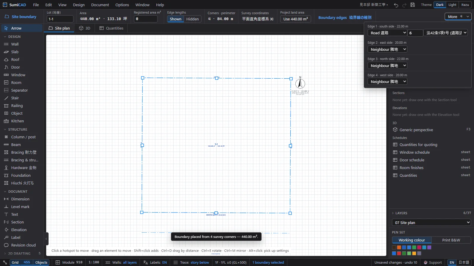
The site plan opens with the boundary selected. Click Use 440.00 m² (Project land area). Under Boundary edges (More when they do not fit) every edge names its side: set the south side edge to Road 道路, 6 m, 法42条1項1号. Without a map position and a road, the access map 付近見取図 and the slant-plane checks stay empty.
5. Grid
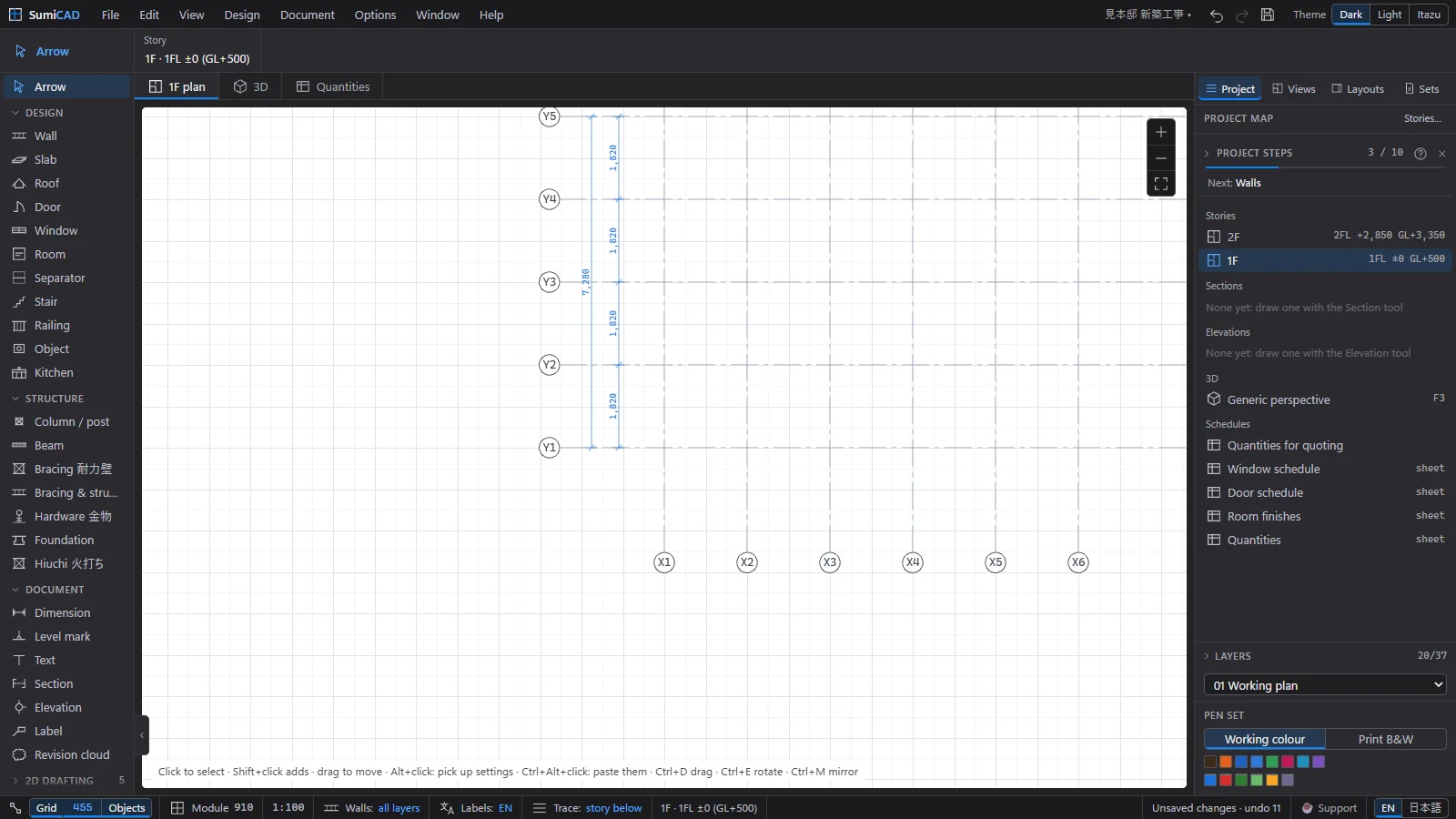
Options › Grid & module…: X axes 6 × 1,820, Y axes 5 × 1,820, Generate. Then click 1F in the Navigator.
6. Walls and their build-up
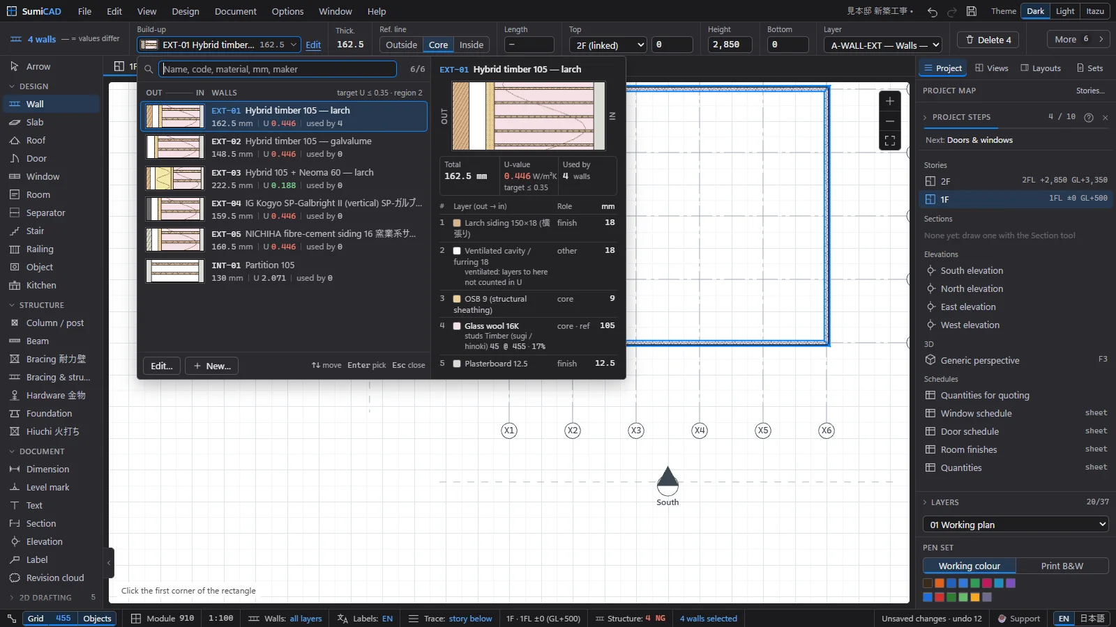
Press W (Wall tool), click Rectangle in the Info Box, click the X1/Y1 corner and the X6/Y5 corner: four walls. Ctrl+A selects all, the walls chip keeps only the walls; open the Build-up picker and choose one whose U value meets the target (green), here EXT-03.
7. Partitions and rooms
W again, Single, build-up INT-01 Partition 105, and draw the partitions. Press Z (Room tool) and click inside each space. Select each room and type its Name (the list suggests LDK, Bedroom, Tatami room…; the Japanese name follows: 寝室, 和室). For the entrance click Doma 土間; for the tatami room More › Tatami 畳敷き › On.
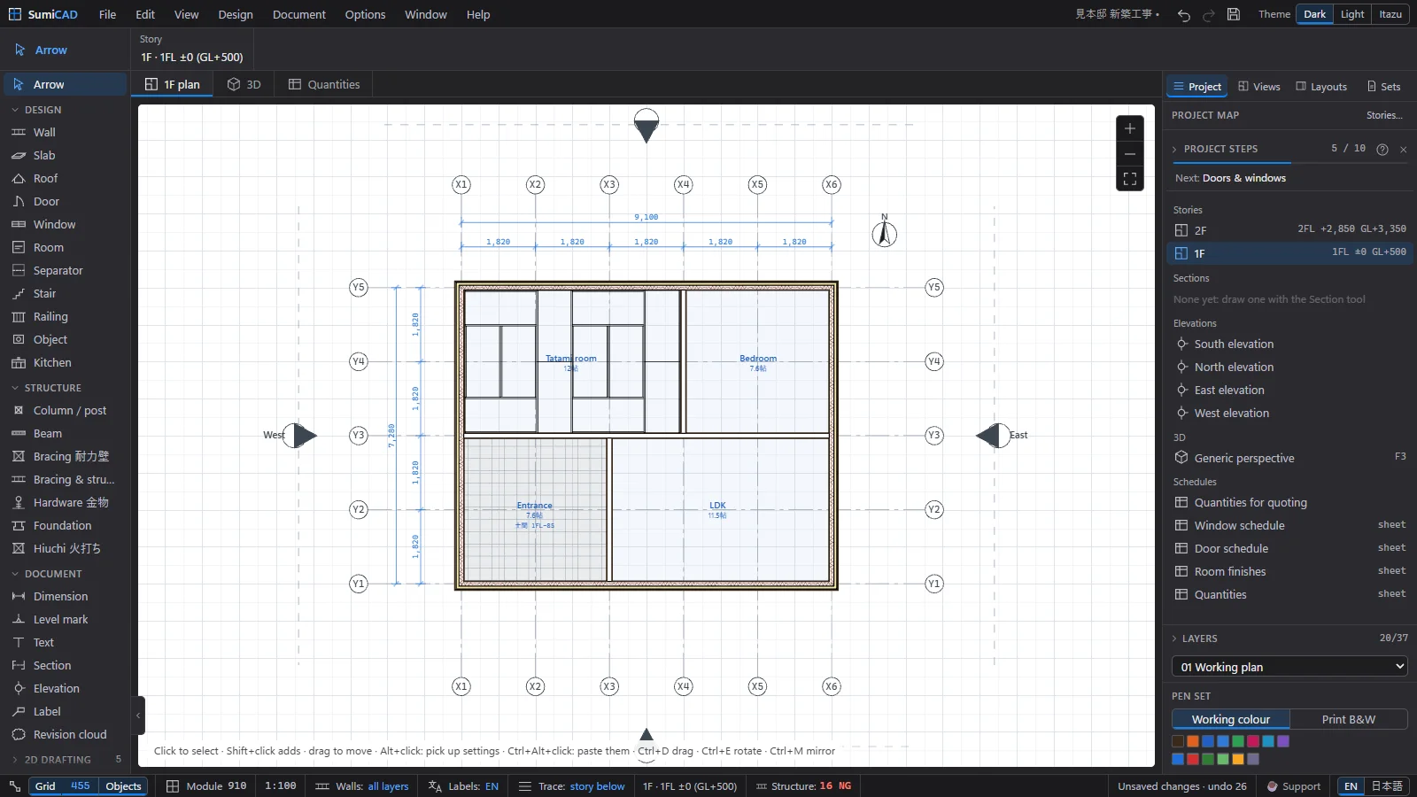
8. Doors and windows
Press N (Window) and click on the walls; press D (Door) for the entrance door. Select a window: More shows the catalogue product and its frame colours Out (外観色) and In (内観色).
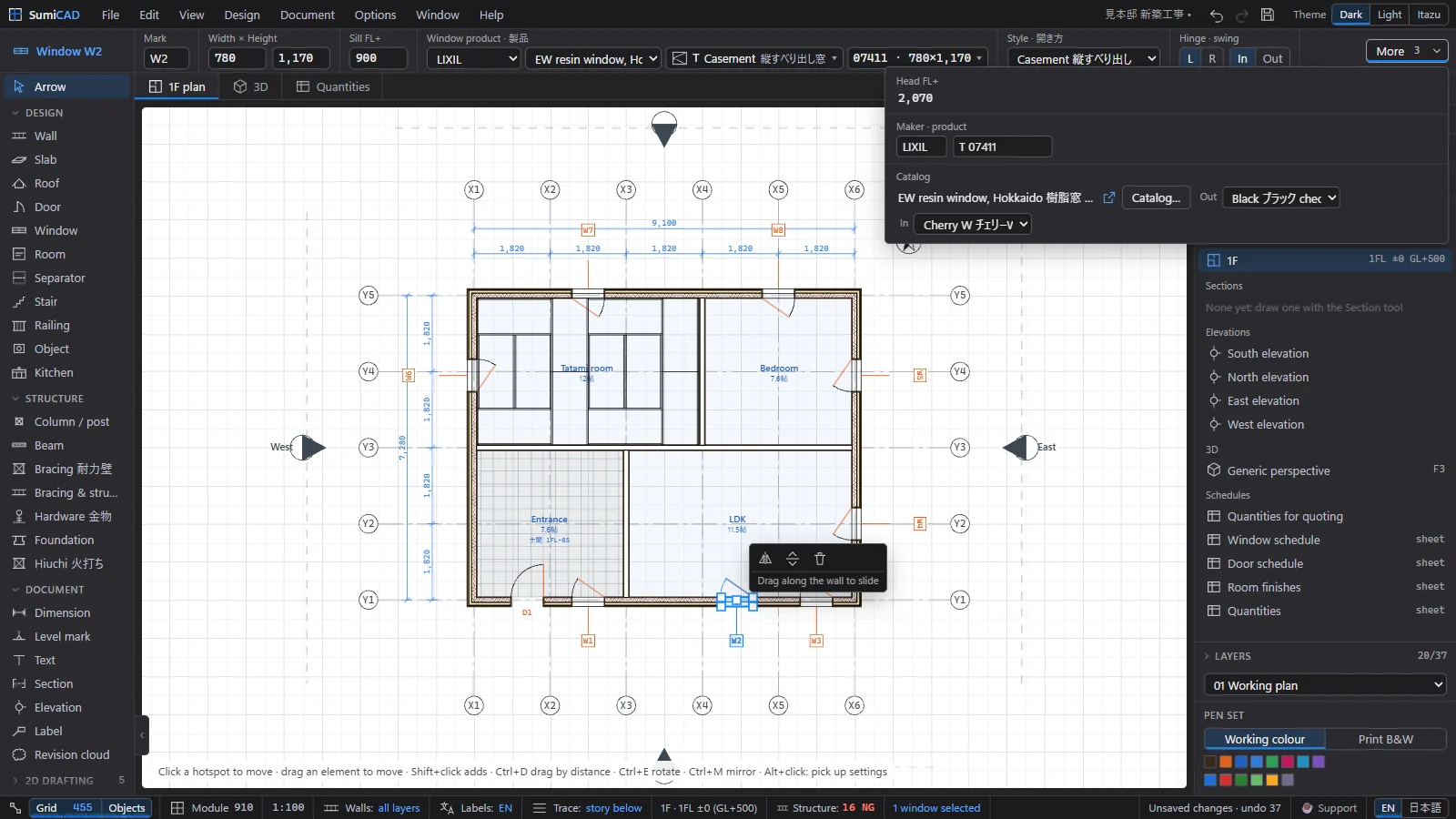
9. Floor and stair
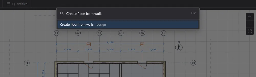
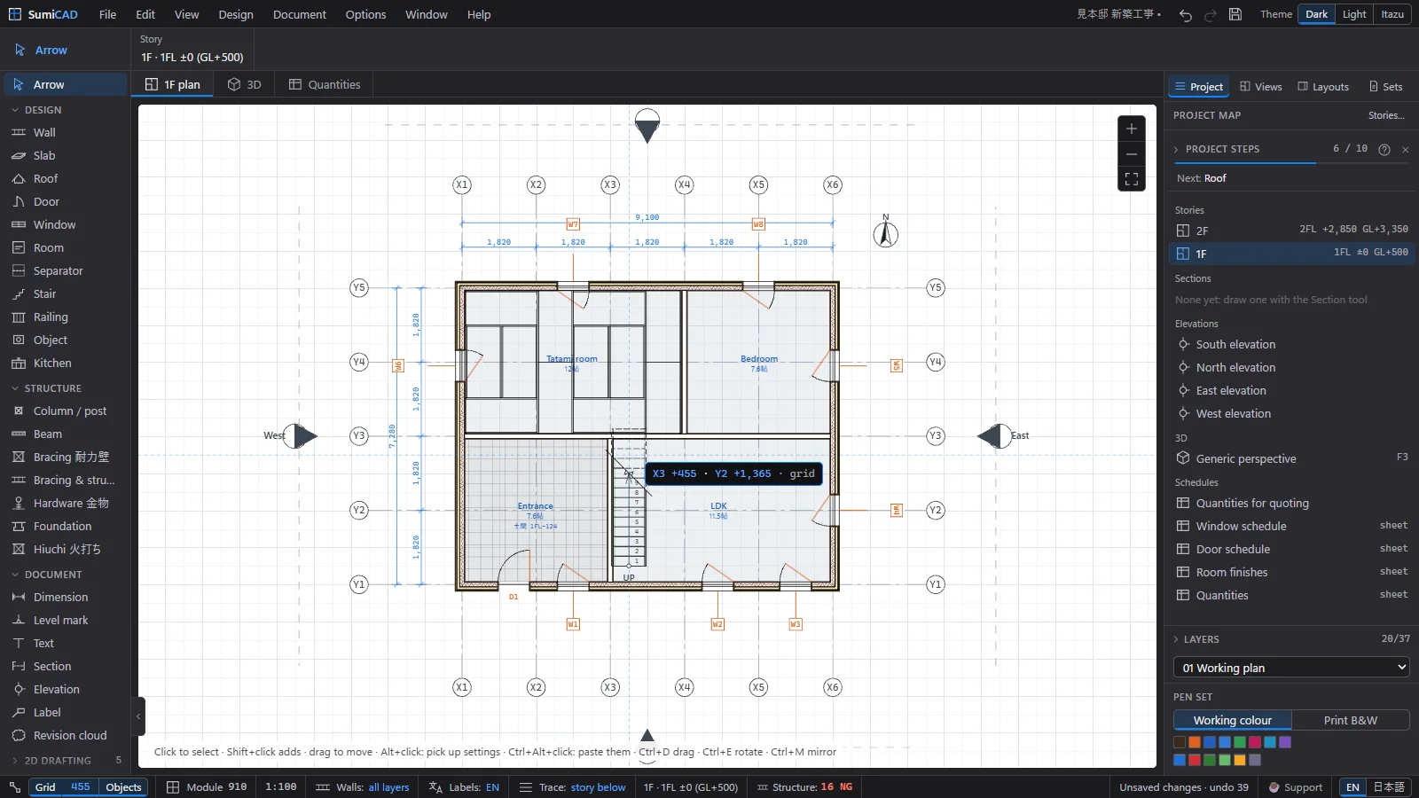
Ctrl+K finds any command: type "floor" and pick Create floor from walls. Then press I (Stair) and click the start and the end of the flight; the Info Box checks 令23・25条 live.
10. The upper floor
Ctrl+↑ goes to 2F. Draw the outer walls (Rectangle), a partition, the rooms and the windows as on the 1F.
11. Roof
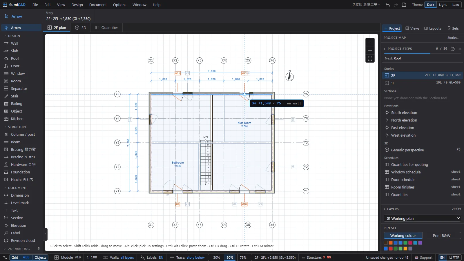
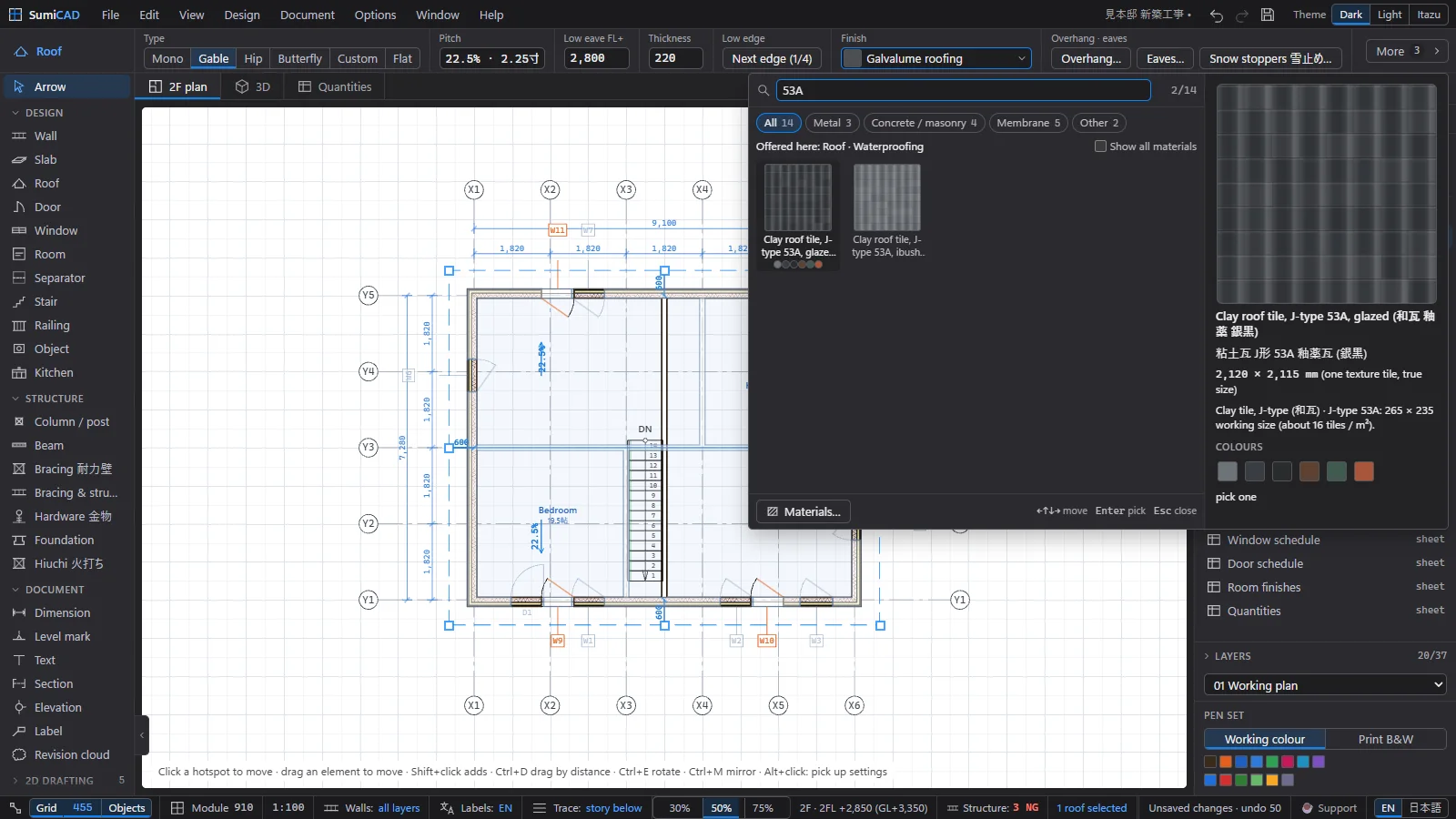
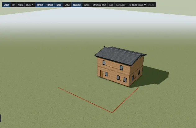
Click Next: Roof (it switches to the top floor and the Roof tool), click Gable, then hold Space and click inside the walls: the roof covers them with its overhang. Select the roof and pick a Finish from the picker (here a J-type 53A kawara). F3 shows the house in 3D.
12. Structure
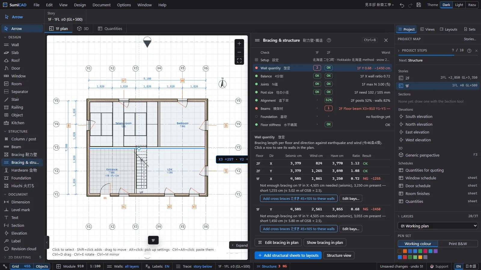
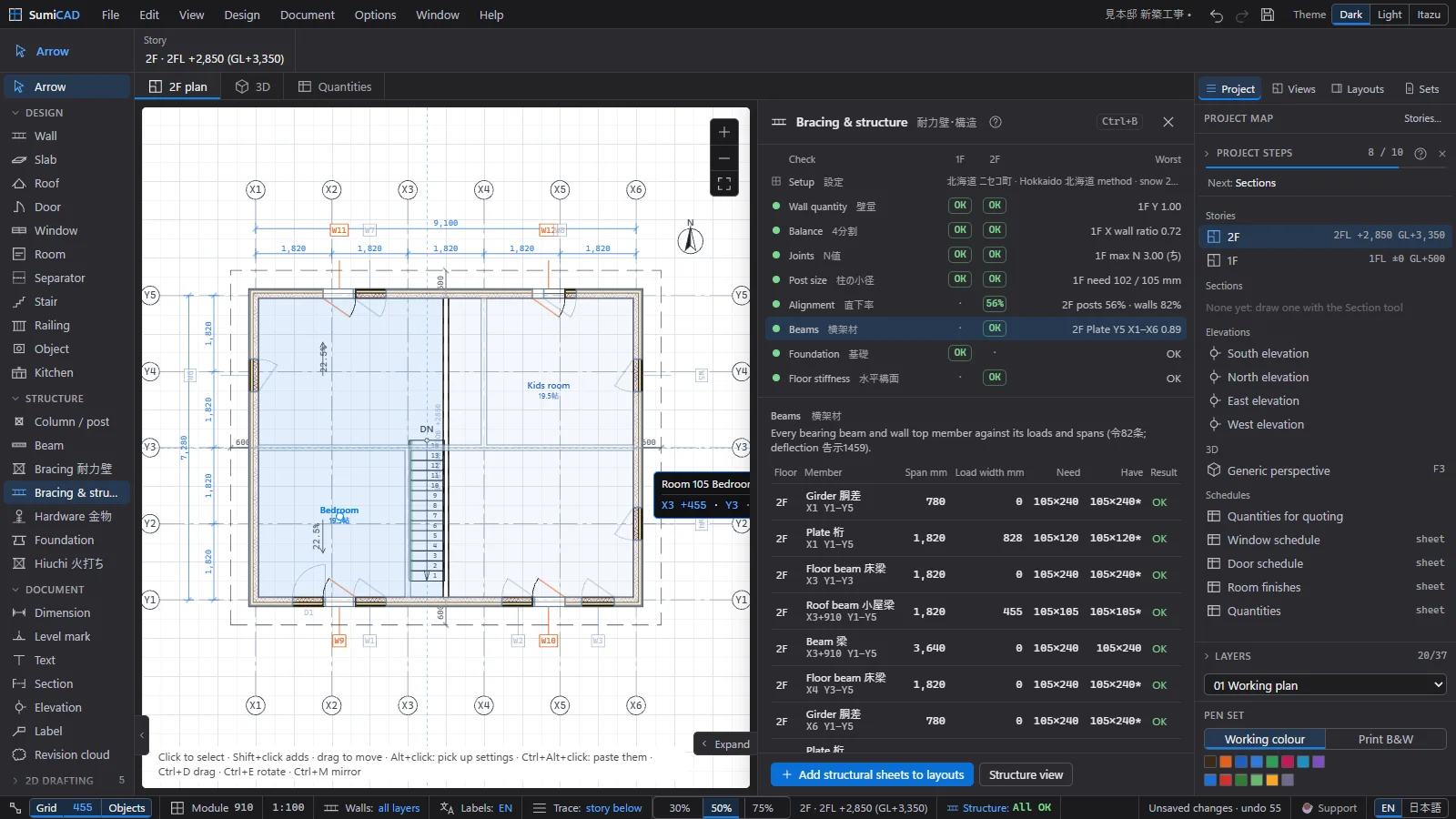
Ctrl+B opens Bracing & structure. On the Foundation step click Foundations under walls. Each NG row explains why and offers its fix (for example Add cross braces たすき, use advised size): click it, and the status bar chip Structure: turns to All OK.
13. Sections
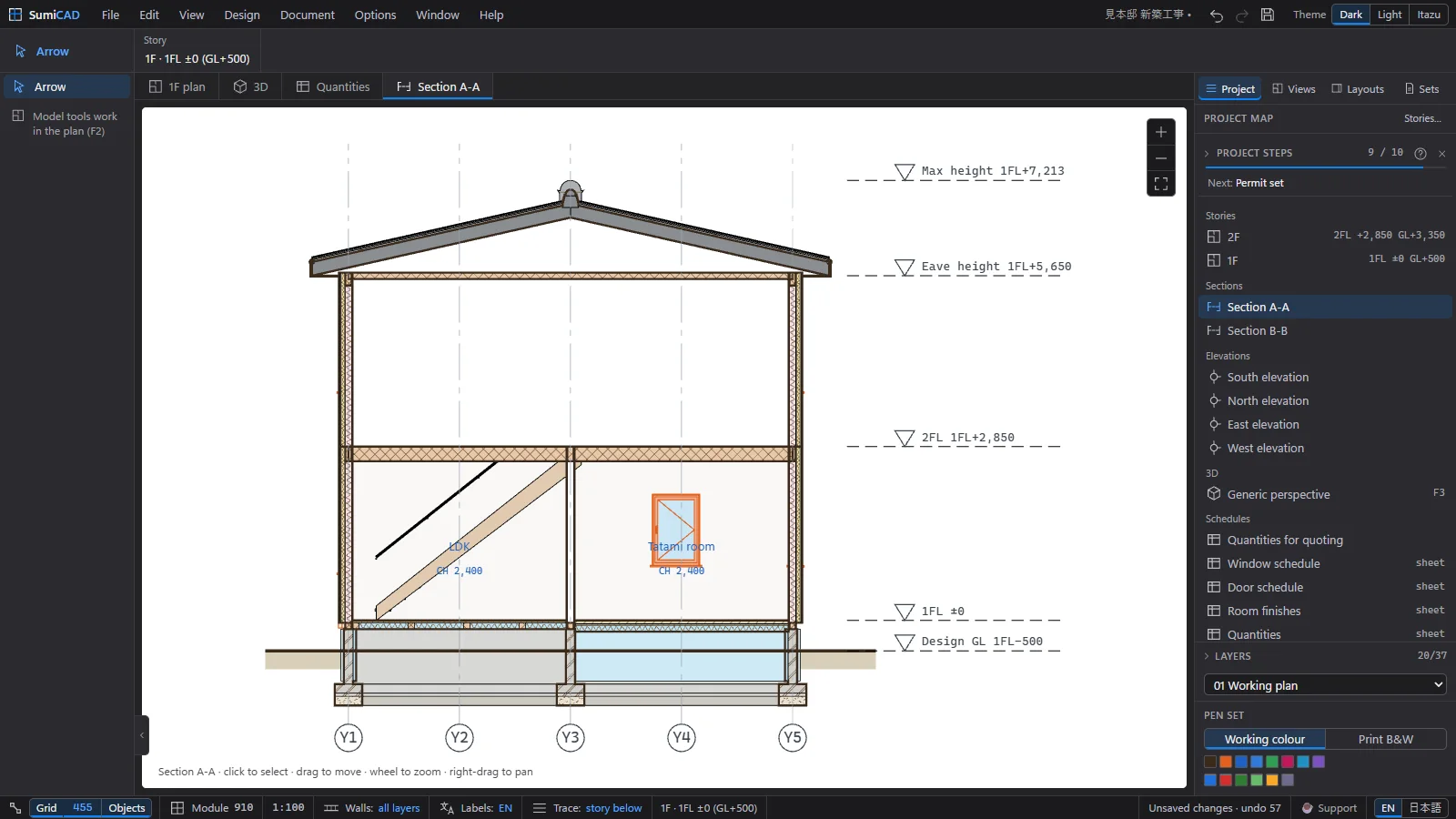
Press X (Section) and draw two cut lines across the house (the permit needs two 断面図). Open them from the Navigator (Section A-A).
14. Permit data and checks
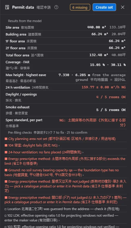
Document › Permit data 確認申請… › Create set builds the P.* sheets. The pre-filing checks 申請前チェック list what is still missing; a row with › opens the panel or tool that fixes it, the others are fields further down in Permit data (city planning, energy, timber species…).
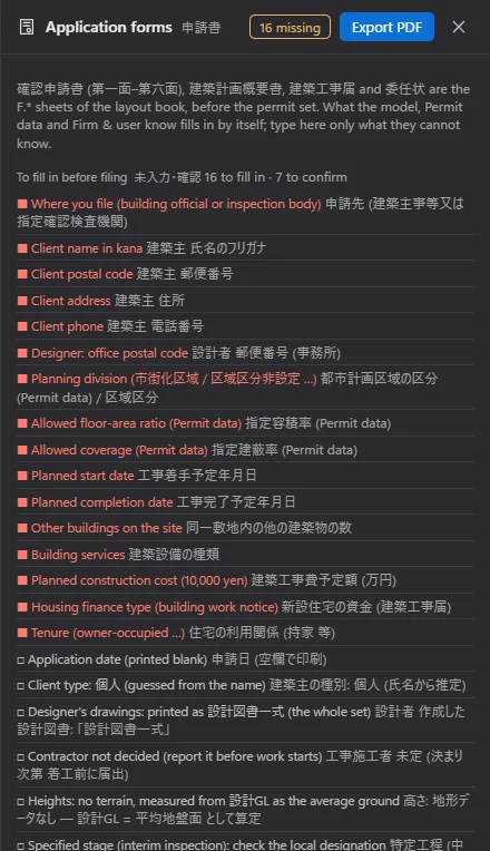
Then File › Application forms 申請書… fills the forms 第二号様式 … from the model; type only what it cannot know.
15. Publish and save
Ctrl+Shift+P (Publisher): Set = Permit 確認申請 P.*, One combined PDF, Publish. Every sheet is on the book's paper (A3 landscape) at true scale. Ctrl+S saves the project.
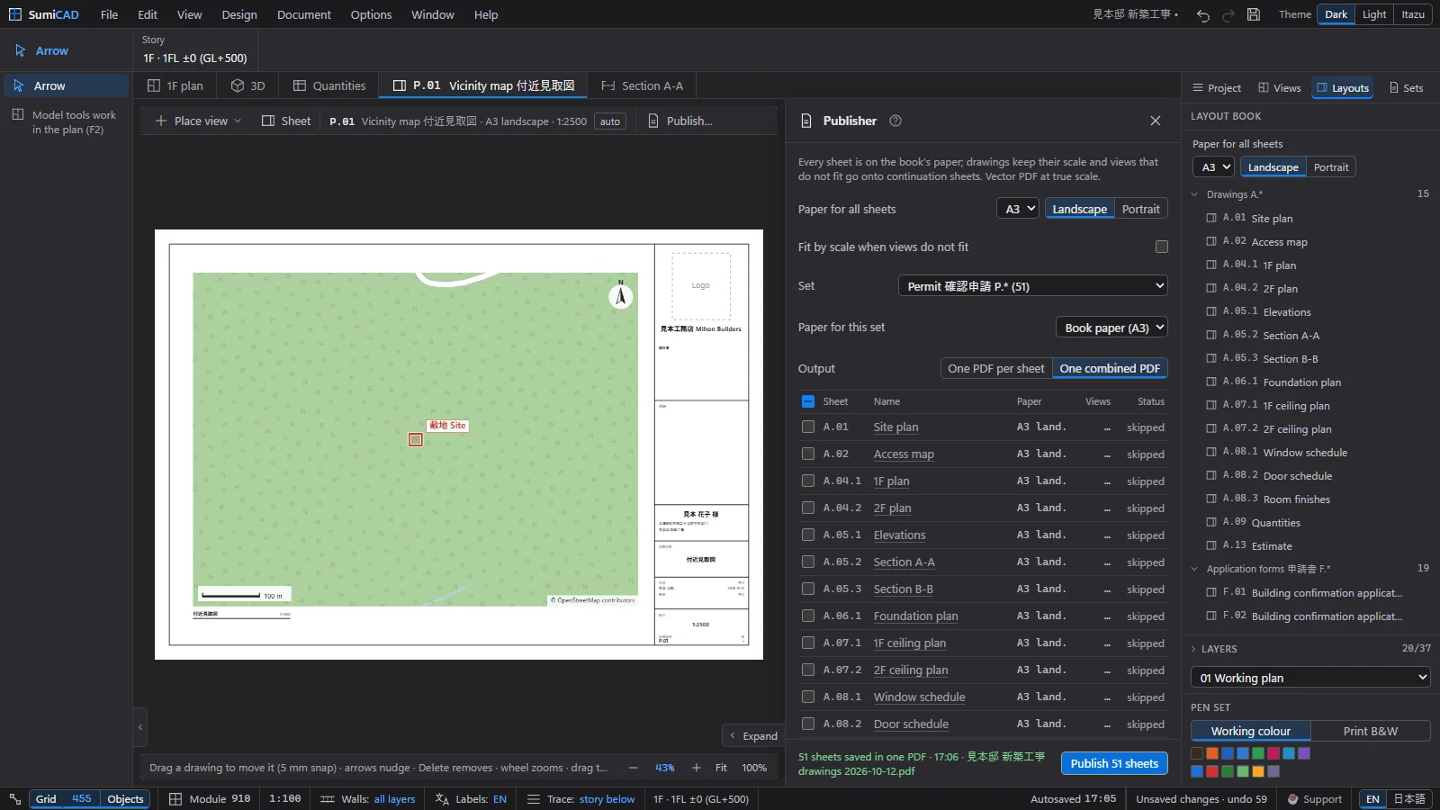
You should now see: PROJECT STEPS 10 / 10. Next: the screen, structure and the permit set in detail.